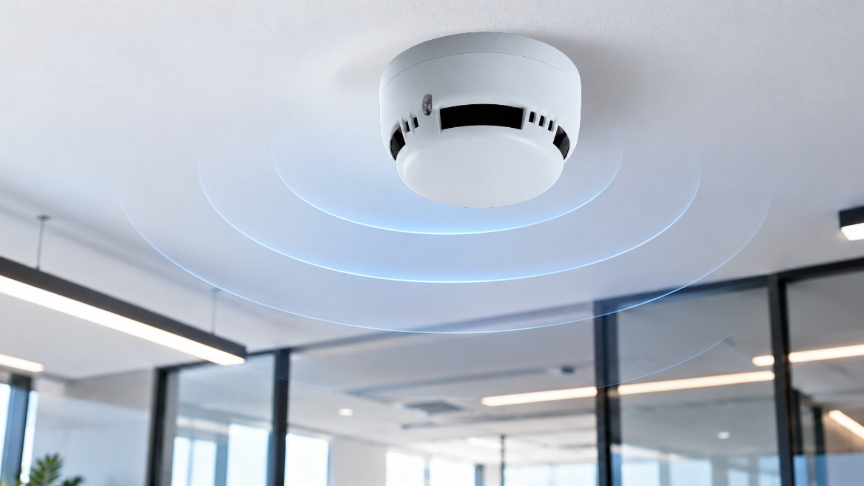
Correct fire detector placement is not simply a matter of positioning devices at equal intervals across a ceiling. The way smoke and heat reach the ceiling can be directly affected by ceiling height, beam geometry, airflow, suspended ceilings, racking, mechanical services and environmental conditions.
For this reason, detector placement should not be treated as a simple layout exercise on an architectural drawing. It should be approached as a design process that predicts how smoke will actually move within the building. Final placement should be determined according to the applicable design criteria and manufacturer documentation.
|
Factor |
Effect on smoke/heat movement |
Design implication |
|
Ceiling height |
May increase travel time to the detector and smoke dilution |
Technology and positioning should be reassessed |
|
Beam depth and geometry |
May create pockets and barriers beneath the ceiling |
Some pockets may behave as separate detection areas |
|
Airflow |
May move smoke away, dilute it or draw it toward exhaust points |
Detector position should be verified against actual air movement |
The key design principle is simple: a detector should not be placed only according to where a fire is expected to start. It should be positioned where fire products are expected to arrive first and accumulate reliably.
Nominal coverage rules can provide a starting point where the ceiling is relatively flat, major obstructions are limited and airflow is considered normal. When architectural or mechanical conditions change this assumption, simply arranging detectors at equal intervals is not sufficient.
Conditions that may invalidate the flat-ceiling assumption include high or multi-level ceilings, deep beams, dense ductwork and cable trays, large lighting features, high storage racks, strong air currents, thermal stratification and process-generated smoke or vapour.
Before detector placement is finalized, the design team should identify ceiling height, beam direction and depth, diffuser positions, airflow rates, suspended-ceiling voids, rack and machinery heights, as well as environmental conditions such as dust, humidity, vapour and temperature.
|
Information required before placement |
Why it matters |
|
Ceiling height and level changes |
To understand smoke travel distance and accumulation points |
|
Beam depth, spacing and direction |
To determine whether ceiling pockets divide smoke movement |
|
Supply and exhaust locations |
To evaluate potential changes in smoke direction |
|
Rack, machinery and duct heights |
To identify physical obstructions affecting coverage |
|
Environmental conditions |
To assess false alarm risk and detector technology selection |
A diffuser or duct added later can change how smoke moves around an existing detector.
Smoke produced by a fire mixes with the surrounding air as it rises. In larger volumes, the time required for smoke to reach the ceiling may increase and its concentration may decrease. A high ceiling therefore represents more than simply a larger space; it can also create a more challenging detection environment.
Three issues are particularly important in high spaces: smoke travel time, dilution and thermal stratification. Under certain conditions, smoke may spread horizontally before reaching the highest ceiling level. In such cases, the suitability of a conventional point detector arrangement should be reconsidered.
|
Condition |
Possible risk |
Approach to consider |
|
Long smoke travel distance |
Delayed alarm |
Detection objective and technology selection |
|
Smoke dilution |
Lower signal at point detectors |
Beam or aspirating smoke detection |
|
Thermal stratification |
Smoke may spread before reaching the ceiling |
Multi-level assessment and field verification |
|
Maintenance access |
Difficult testing and cleaning |
Accessible or remote test methods |
Detection technology for high ceilings should be selected according to the geometry and risk of the space. Point smoke, point heat, beam smoke and aspirating smoke detection are not intended for identical applications.
|
Technology |
Where it may be advantageous |
Critical check |
|
Point smoke detection |
Typical ceiling heights and clean environments |
Diffusers, obstructions and false alarm sources |
|
Point heat detection |
Environments unsuitable for smoke detection |
Temperature class and detection delay |
|
Beam smoke detection |
Large and high-volume spaces |
Beam path, alignment and stratification |
|
Aspirating smoke detection |
Early detection or difficult-access areas |
Pipe network, sampling and airflow |
Maximum installation heights and detector spacing can vary according to product class, application and the applicable standard. Unverified numerical values should therefore not be treated as universal project rules.
Beams can restrict horizontal smoke movement beneath a ceiling. Deep or closely spaced beams may divide the ceiling into partially independent pockets. Smoke can accumulate in one pocket while taking longer to reach a detector located in another.
Beam analysis should therefore not be performed only from the plan view. Ceiling and beam geometry should also be reviewed in section.
Beam depth, spacing, pocket area, smoke transfer openings and combined obstructions such as ducts, cable trays or lighting elements should be evaluated together.
For example, a room may originally be designed with four evenly spaced detectors. If deep beams are later introduced and divide the ceiling into eight separate pockets, the floor plan may remain unchanged while the smoke path changes significantly.
The correct response is not simply to reduce the spacing between detectors. The designer should determine whether the new ceiling pockets behave as separate detection areas.
A common mistake is to move a detector to the underside of a beam and assume that all surrounding pockets are then covered. A detector beneath the beam may not detect smoke accumulating above the beam edges early enough in every condition.
Smoke does not move only because of buoyancy. Air currents generated by HVAC systems can significantly influence its direction.
A supply diffuser may move smoke away from a detector or push it downward from the ceiling. Exhaust or return air may draw smoke toward a particular area. However, placing a detector directly beside an exhaust opening is not automatically correct either, because dilution, contamination and different HVAC operating modes must also be considered.
|
Air element |
Possible effect |
What should be checked |
|
Supply diffuser |
Disperses smoke or pushes it downward |
Throw direction, airflow rate and direct air impact |
|
Exhaust / return |
May draw smoke toward the opening |
Behaviour when HVAC is off and contamination risk |
|
Jet fan |
Creates high-speed directional airflow |
Fire and smoke-control scenario |
|
Door / pressure difference |
May move smoke into adjacent spaces |
Door-open and door-closed scenarios |
The distance from a diffuser should not be considered as a single universal number. The actual assessment should consider diffuser type, throw direction, airflow rate, ceiling height and HVAC behaviour during a fire condition.
Airflow may be evaluated using mechanical drawings, airflow schedules, suitable local airflow observations, anemometer measurements, different HVAC operating modes and, where necessary, engineering analysis.
Smoke pencils or test aerosols can help indicate local airflow direction, but they do not fully reproduce real fire dynamics.
Detector placement should not be assessed only at the visible ceiling level. Suspended-ceiling voids, raised floors, high storage racks, cable trays, large ducts and equipment enclosures can alter smoke movement.
Where cables, electrical equipment or combustible materials are present above a suspended ceiling, the void may require separate assessment. Similarly, where cables and pressurised air exist below a raised floor, smoke may travel along a different route.
High storage racks can delay smoke rising toward the ceiling or retain it at intermediate levels. For this reason, ceiling-level detection alone should not automatically be assumed to provide adequate coverage in every warehouse configuration.
Maintenance access is also part of detector design. A correctly positioned detector that cannot be safely tested, cleaned or replaced may not remain reliable throughout its service life. Access panels, test points, address labels and remote testing arrangements should therefore be considered during design.
The same detector type is not suitable for every environment. Dust, vapour, humidity, high temperature, condensation and process-generated particles can directly affect detection performance.
Dusty environments may lead to contamination and false alarms. Vapour may cause unwanted alarms in optical smoke detectors. High-temperature environments may require careful heat detector class selection, while cold or condensing environments may affect optical and electronic components.
|
Environmental factor |
Possible result |
Design approach |
|
Dust |
Contamination and false alarms |
Suitable technology and maintenance |
|
Vapour / humidity |
Unwanted optical alarms |
Change in position or detector technology |
|
High temperature |
Incorrect heat detector class |
Appropriate class and alarm temperature |
|
Cold / condensation |
Electronic and optical effects |
Environmental suitability and protection |
When false alarms occur, the solution should not simply be to move the detector away from the risk or reduce sensitivity. The false alarm source, detector technology, airflow and maintenance condition should be analysed together.
Before detector placement is finalized, architectural, mechanical and fire detection drawings should be reviewed together.
Architectural checks should include ceiling levels, beams, suspended ceilings, concealed voids, racks and maintenance access. Mechanical checks should include supply, return and exhaust diffusers, airflow rates and different HVAC operating modes.
On the fire detection side, detector technology should be verified against environmental conditions. Solutions for beam pockets and high-volume areas should be justified, while loop information, device addresses, testing requirements and maintenance access should also be confirmed.
|
Site acceptance check |
What should be verified? |
|
Position |
Does the actual device location match the as-built drawing? |
|
Obstruction |
Do ducts, trays, lighting or signs affect the detector? |
|
Airflow |
Is local airflow acceptable under relevant HVAC modes? |
|
Function |
Has detector response been verified with an appropriate test method? |
|
Access |
Can testing, cleaning and replacement be performed safely? |
If the ceiling, diffusers, racks or process layout changes, detector placement should be reassessed. Even if the fire alarm system itself has not been physically modified, the smoke path may have changed.
A detector location that appears correct on a drawing may not perform in the same way after installation is complete.
Diffusers, ducts, lighting fixtures, storage racks or signage added later may change the smoke path.
For this reason, commissioning should verify device position, airflow conditions, accessibility and detector response together.
Does detector coverage increase as the ceiling gets higher?
No. Higher ceilings may increase smoke travel time and dilution. Detector technology and placement should be reassessed.
Does every beam pocket require a detector?
Not always. Beam depth, spacing, pocket area and applicable project criteria should be evaluated together.
Can a detector be installed next to an air diffuser?
Direct airflow may move smoke away from the detector or dilute it. Distance, throw direction, airflow rate and HVAC operating mode should be considered together.
Which detector should be used for high ceilings?
Point, beam, aspirating or other detection technologies may be considered depending on the risk and geometry. There is no single universal solution.
Is detection required above a suspended ceiling?
The decision depends on the equipment, cabling, fire load, airflow, void height and applicable project requirements.
Is ceiling-only detection always sufficient in a racked warehouse?
Not always. Racking can delay or retain smoke and may create a need for intermediate-level or in-rack detection.
Does a smoke test prove that detector placement is correct?
It is useful for evaluating function and local airflow, but it does not replace the applicable design standard or engineering analysis.
Should fire detection drawings be updated when the mechanical design changes?
Yes. Changes to diffusers, ducts, jet fans or pressure conditions can alter smoke movement and should trigger a review of detector placement.
Correct detector placement is not simply about creating equal spacing across a ceiling.
Ceiling height, beam geometry, airflow, suspended ceilings, racking and environmental conditions should all be considered together.
The objective is to predict how smoke and heat will actually move through the building, select the appropriate detection technology, position it correctly and verify the result under real site conditions.
• CEN/CENELEC and TSE — current CEN/TS 54-14 or applicable fire detection planning/design standard.
• NFPA LiNK — current NFPA 72 edition where contractually applicable: https://link.nfpa.org/
• Binaların Yangından Korunması Hakkında Yönetmelik — current official text: https://www.mevzuat.gov.tr/
• Finder current detector datasheets, installation manuals, compatibility lists and application notes.
 TR
TR