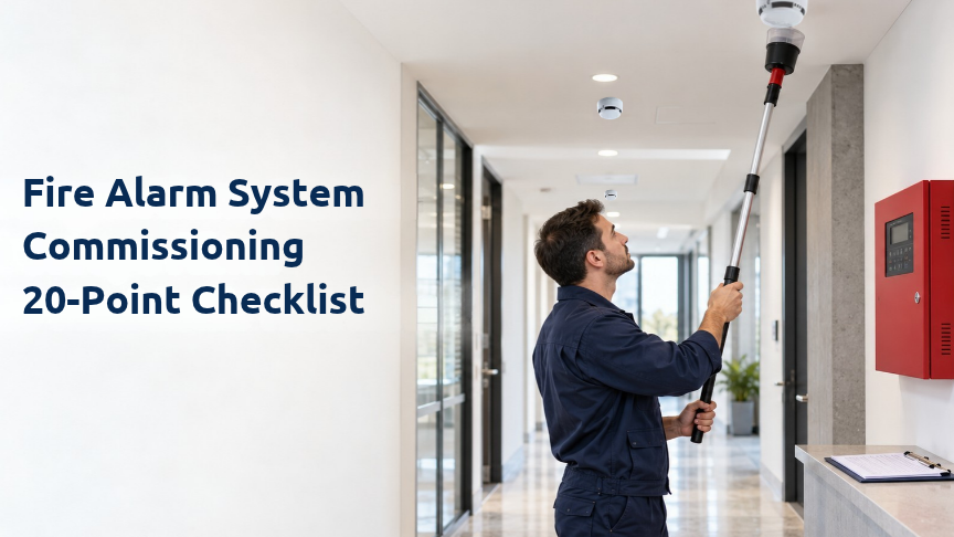
Commissioning is not a few alarm activations at the control panel. Approved drawings, device addresses, loops/zones, alarm and fault functions, standby power, audible/visual alarms, manual call points, remote transmission and all cause-and-effect interfaces such as BMS and HVAC must be verified end to end. The final step is documented closure of deficiencies and a handover package that allows the site team to operate and maintain the system safely.
A system can be well installed yet fail its intended function because of incorrect configuration, wrong labels, missing interfaces or untested fault behaviour. Commissioning proves that the approved design has been realised on site. CEN/TS 54-14:2018 addresses planning, design, installation, commissioning, use and maintenance as one lifecycle. NFPA 72:2025 also contains dedicated requirements for documentation and inspection, testing and maintenance. The project must state which standards, local regulations and authority requirements govern acceptance.
This checklist is a general commissioning and handover guide. It does not replace the approved design, specification, manufacturer instructions, authority requirements or the project-specific acceptance procedure. Test quantities, methods, thresholds, durations and pass/fail criteria must be verified for the actual project.
|
Gate |
Check |
Do not proceed until |
|
Documents ready? |
Approved drawings, device schedule, address/zone plan, cause-and-effect matrix, cable routes and current revisions are available. |
Functional testing can be traced to an approved baseline. |
|
Site ready? |
Installation is complete, devices are accessible, temporary works are identified and interfacing trades are ready. |
Interface acceptance can be performed safely. |
|
Test plan approved? |
Test roles, witnesses, methods, records and deficiency closure process are defined. |
Handover can be evidenced and signed. |
Do devices, cables, modules and interfaces match the latest approved design? Are field changes captured in as-built drawings?
Evidence and record: Revision + field record.
Panel model, firmware/software, date/time, access levels, network nodes and configuration backup verified?
Evidence and record: Config printout/backup.
Does every address identify the correct physical location and zone at the panel/annunciator?
Evidence and record: Address list + screen record.
Any open, short, earth/ground fault or reversed connection? Shielding/earthing per approved design?
Evidence and record: Measurement/test record.
Correct detector/base, position, obstruction clearance, covers removed and maintenance access available?
Evidence and record: Visual inspection form.
Using an approved test method, does the detector produce the correct alarm, address, zone, text and event sequence?
Evidence and record: Test result + timestamp.
Does each call point operate, report the correct location and reset correctly, with suitable access?
Evidence and record: MCP test record.
Do sounders or voice alarm functions operate in the correct scenario and area? Where required, are acoustic/intelligibility measurements recorded?
Evidence and record: Functional/measurement form.
Do visual alarm devices operate in the correct zone/scenario, with required circuit and synchronisation behaviour?
Evidence and record: Functional record.
Do alarm, pre-alarm, delays, confirmation, silence, reset and outputs follow the approved sequence?
Evidence and record: Signed C&E test table.
Do hold-open devices, door releases, turnstiles or locks move to the intended safe state?
Evidence and record: Interface test record.
Do fan, damper, jet-fan and smoke-control commands operate for the correct zone; are feedback signals correct?
Evidence and record: Joint BMS/HVAC record.
Do lift recall, escalators, generators or other connected systems respond according to the fire strategy?
Evidence and record: Multi-trade test record.
Where applicable, are suppression panels, pre-action, gaseous systems, kitchen suppression or process shutdown I/O safely verified?
Evidence and record: Interface/I-O record.
Do fire, fault and required supervisory signals reach security, BMS or remote monitoring with the correct priority and text?
Evidence and record: Send/receive comparison.
On loss of mains, does the system transfer to standby power correctly, indicate the fault and recover properly?
Evidence and record: Power test record.
Are selected open/short circuit, device loss, network fault and isolator behaviours correctly indicated and contained?
Evidence and record: Fault-scenario form.
Do silence, reset, disable/enable, test mode and user permissions work without allowing unsafe operation?
Evidence and record: Access/function check.
Are alarm, fault, disablement and reset events logged with correct time and device information; can records be exported?
Evidence and record: Event-log export.
Has operator training been completed and are as-builts, schedules, test reports, backups, maintenance plan and open-item status handed over?
Evidence and record: Signed training/handover record.
“Tested / OK” is not sufficient evidence by itself. A record should allow another technician to reproduce the test and understand what was expected and what actually occurred.
|
Record field |
Example |
|
Test ID |
T-021 / Loop 2 / Device 034 |
|
Date and time |
02 Sep 2026 10:42 |
|
Tester / witness |
Technician + consultant/facility representative |
|
Stimulus method |
Approved smoke aerosol / heat tester / call-point key |
|
Expected result |
Panel alarm + zone 3 sounders + BMS fire signal |
|
Actual result |
Alarm 10:42:16; BMS 10:42:18; sounders active |
|
Result |
PASS / FAIL / N.A. |
|
Action |
For FAIL: owner, due date and retest ID |
Do not declare overall acceptance complete while failed tests remain open. After correction, repeat the same functional test and retain the original failed result with its closure evidence.
Fire alarm systems often exchange commands and status with other building systems. Acceptance is therefore not a fire-panel-only activity. Electrical, mechanical, BMS, lifts, security and suppression teams may need to attend the same test window.
Fire alarm behaviour: Alarm + correct location + programmed outputs. Interfaced system: Sounder/VAD. Feedback to verify: Correct output and area.
Fire alarm behaviour: Alarm + smoke-control command. Interfaced system: HVAC / jet fans. Feedback to verify: Command + status feedback.
Fire alarm behaviour: Alarm + release output. Interfaced system: Access/door controls. Feedback to verify: Door moves to intended safe state.
Fire alarm behaviour: Defined output/relay. Interfaced system: Lift system. Feedback to verify: Recall sequence completed.
Fire alarm behaviour: Defined monitoring/warning. Interfaced system: Suppression panel. Feedback to verify: Correct signal/state.
Fire alarm behaviour: Fault + remote indication. Interfaced system: BMS/remote monitoring. Feedback to verify: Fault received at correct priority.
The system must make wiring and power problems visible, not only fires. Fault simulation during commissioning must be controlled, reversible and planned so that it does not accidentally trigger real suppression or critical process actions.
Record transfer to standby power and fault indication when mains power is removed.
Verify battery connection, charging and design adequacy according to the approved project and manufacturer requirements; open-circuit voltage alone is not enough.
Simulate selected open/short circuit faults to observe affected devices and isolator behaviour.
For networked systems, include panel/node loss and communication fault scenarios.
Record how the system returns to normal after the fault is restored.
Testing detector alarms but skipping fault scenarios.
Failing to compare panel location text with the real physical location.
Issuing “final” as-built drawings before field changes are incorporated.
Accepting BMS/HVAC/lift integration on paper without joint functional tests.
Triggering real suppression or critical process outputs without an approved safe-test plan.
Treating battery voltage as a complete standby-power test.
Leaving devices or modules disabled at handover.
Deleting failed test records and keeping only a clean PASS list.
Failing to synchronise event-log time with BMS/security systems.
Reducing operator training to a signature sheet instead of practising alarm, fault, silence and reset scenarios.
No. Commissioning verifies that a new or materially modified system matches the approved design and performs correctly before acceptance. Periodic maintenance preserves performance during operation.
The scope is defined by the approved project, applicable standard, specification and authority. The commissioning plan should account for every installed device; any sampling approach must have a documented basis.
Not by itself. Signal type, location, priority, delay, feedback and reset behaviour should be verified end to end.
No. Standby-power design, connections, charging, load behaviour and the project-defined standby/alarm duty must be verified together.
Record the defect, owner and target date, correct the issue, then repeat the same functional test and retain closure evidence.
Not always. Safe functional verification should follow the approved manufacturer/project test procedure; a live discharge is performed only where specifically required.
Panel/network configuration backup, as-built drawings, address schedules and the cause-and-effect matrix are core continuity records.
Verify local regulation, contract/specification, authority requirements and the current standards explicitly adopted for the project.
The value of a test lies not only in the alarm obtained on the day, but in a traceable record of expected and actual behaviour. When a device address, zone, panel message and operated outputs are considered together in the test record, facility and service teams can later see the conditions under which that function was verified. The configuration backup, as-built drawings and cause-and-effect matrix should be handed over with these records.
The records are handed over to the facility team.
CEN/TS 54-14:2018 — Fire detection and fire alarm systems: planning, design, installation, commissioning, use and maintenance — https://knowledge.bsigroup.com/products/fire-detection-and-fire-alarm-systems-guidelines-for-planning-design-installation-commissioning-use-and-maintenance-1
NFPA 72:2025 — National Fire Alarm and Signaling Code — https://link.nfpa.org/all-publications/72/2025
Turkish fire safety legislation — https://www.mevzuat.gov.tr/
Current Finder product, installation, programming and service documentation — https://www.finder.com.tr/
 TR
TR