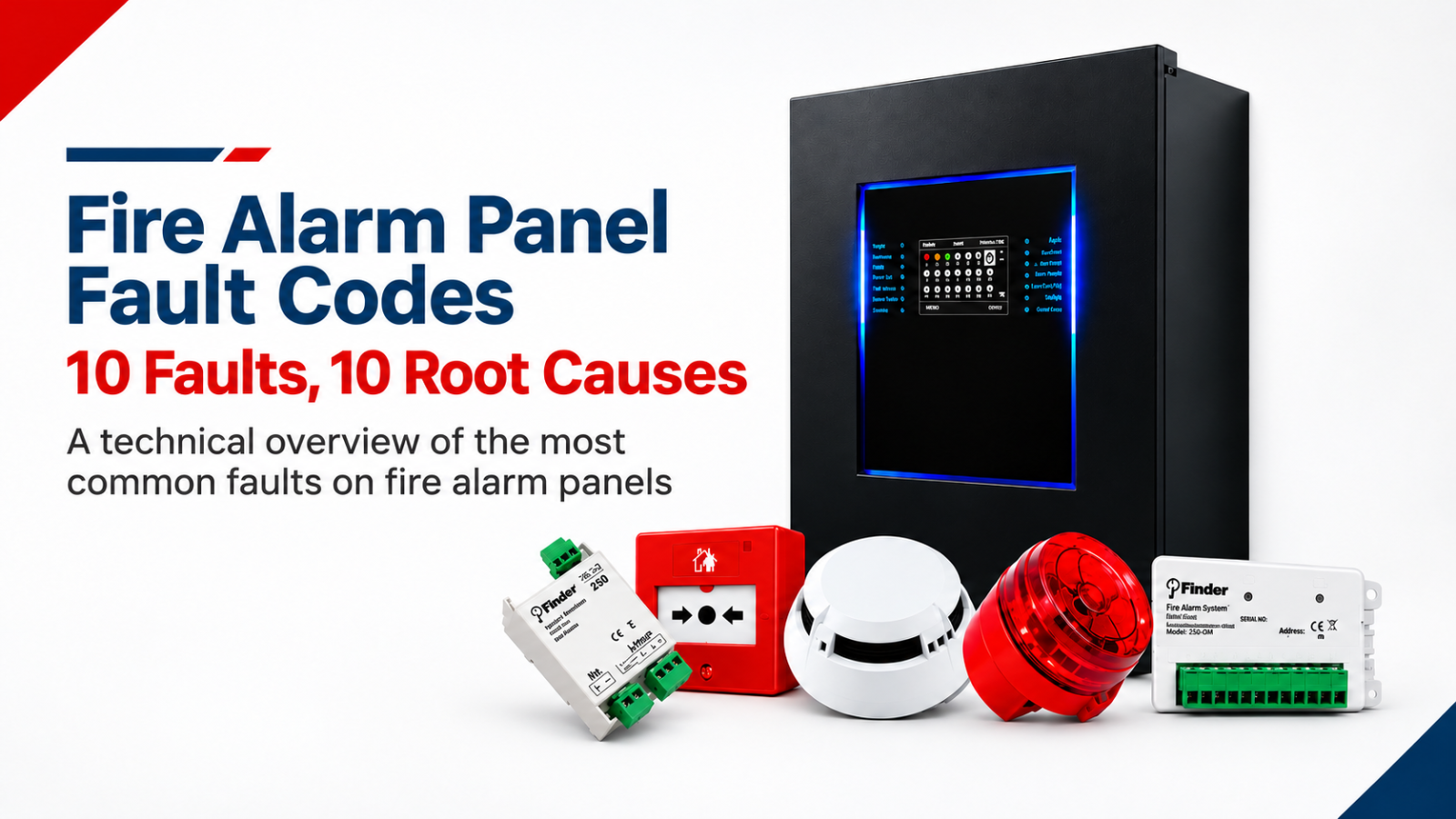
A FAULT indication on a fire alarm panel does not automatically identify the failed component. It indicates that an expected condition or supervised function is not normal. Correct diagnosis requires the exact displayed message, event timestamp, affected loop, zone or address, the scope of the fault and any site changes immediately preceding the event to be considered together.
The same symptom may appear with different wording or codes depending on panel model, firmware version or project configuration. The ten headings below are therefore model-independent fault categories, not exact Finder display codes. The current Finder user or service documentation for the relevant panel model and software version should be used for exact messages, thresholds and service actions.
The most important distinction is that the panel message, fault scope, root cause and corrective action are not the same thing. A “loop fault” indicates that the system has detected an abnormal condition on a loop. The actual cause may be an open circuit, short circuit, isolator operation, field-device problem, wiring error or recent site intervention.
The purpose of the first response is therefore not simply to silence the message but to preserve evidence and narrow the scope of the fault.
The panel message describes the symptom detected by the system. “Battery fault”, “device missing” or “earth fault” is the starting point of diagnosis.
Fault scope determines whether the problem is concentrated in one device, one loop, a sounder circuit, the network or the power supply.
The root cause is the actual technical reason: a broken cable, loose terminal, weak battery, incorrect address or a connection problem following site work, for example.
Corrective action is the permanent and verified action that removes the root cause.
|
Fault category |
What the panel sees |
Likely root cause |
First safe check |
|
Mains / AC supply |
Expected mains or PSU state is not detected |
Utility outage, breaker/fuse, loose terminal, PSU, maintenance isolation |
Building supply and panel power indications |
|
Battery / charger |
Standby-power or charging condition is abnormal |
Aged battery, loose connection, charger circuit, low capacity |
Battery age and connections |
|
Loop open circuit |
Loop continuity has been lost |
Broken cable, removed device/base, loose terminal, refurbishment |
Affected loop and device range |
|
Loop short / isolator |
Low impedance or short circuit detected |
Crushed cable, wiring error, moisture, metal contact, base/device |
Isolated segment |
|
Device missing |
Configured addressable device is not responding |
Device removed, poor base contact, loop/wiring issue, configuration |
Address versus physical device label |
|
Duplicate address |
Discovered topology does not match device list |
Duplicate address, programming error, uncontrolled auto-learn |
As-built versus panel database |
|
Earth fault |
Unintended connection to earth/screen/chassis |
Insulation damage, moisture, screen, terminal, third-party interface |
Methodical circuit isolation |
|
Sounder / NAC fault |
Open, short or termination problem on supervised output |
EOL, wiring, polarity, sounder/beacon, output protection |
Identify affected output |
|
Network / panel communication |
Panel, repeater or card is unavailable |
Power, network cable, card, node ID, termination, configuration |
One node or network segment? |
|
Detector maintenance/contamination |
Sensor approaches maintenance threshold or behaves abnormally |
Dust, steam, aerosol, ageing, environment, unsuitable detector |
Environment, maintenance history and test |
This table only summarises the diagnostic direction. Mains and power-supply measurements should be performed only by authorised personnel.
A mains or AC supply fault means that the panel does not detect its expected 230 V AC input or power-supply condition.
The first step is to establish whether building power is actually available and to review the panel power indications.
Potential causes include a utility outage, breaker or fuse problem, loose terminal, PSU fault or planned isolation during maintenance.
If mains power is present but the AC fault remains, the panel input, PSU, fuse or monitoring circuit may require further assessment.
A battery fault indicates that the standby-power system considers the battery, connection or charging condition abnormal.
Possible causes include an aged battery, loose or open connection, charging-circuit problem or insufficient capacity.
A normal-looking open-circuit battery voltage does not prove adequate battery capacity. If the fault begins after a mains outage, battery age, charging condition and behaviour under load should be considered together.
A loop open circuit indicates that continuity of the addressable loop has been lost at some point. Typical causes include a broken cable, removed device or base, loose terminal, refurbishment work or incorrect field intervention.
The first step is to record which loop and device range are affected. Identifying the last responding and first missing addresses may help divide the route logically.
In a loop short circuit, the panel detects low impedance or a short. In architectures with isolators, the affected segment may have been separated automatically.
Crushed cable, wiring errors, water or moisture, metal contact and a faulty device or base are possible causes.
Short-circuit isolators or protection functions should not be bridged or disabled to force the system back online.
A “device missing” or “no response” message means that the panel cannot obtain the expected response from a previously configured addressable device.
This does not mean that the device itself has necessarily failed.
The device may have been removed, may not be fully seated in its base, or there may be a local wiring, loop, address or configuration problem.
The first check is to match the panel address with the physical field label and confirm that the device is present and correctly connected.
If a single device repeatedly disappears, the device, base and local wiring become priority checks.
If the discovered device topology does not match the expected device list, two devices may share the same address, a replacement may not have been programmed correctly, auto-learn may have been used without control or the panel may still contain an old configuration.
The as-built address list should be compared with the panel database.
Using auto-learn without first documenting the field change can convert incorrect addressing into the permanent configuration.
An earth fault means that a fire alarm circuit has an unintended electrical relationship with earth, screen or chassis.
Potential causes include damaged cable insulation, moisture, incorrect screen termination, terminal contact or a third-party interface.
Where an earth fault begins after refurbishment, recently altered circuits can be divided methodically to narrow the source.
Protective earth should never be removed simply to make an earth-fault indication disappear. The impact depends on the fault location and system architecture, and the source should be identified and corrected.
A sounder or NAC circuit fault means that the panel has detected an open circuit, short circuit or termination problem on a supervised audible or visual alarm output.
Possible causes include the EOL or terminating component, broken wiring, incorrect polarity, a failed sounder/beacon or output protection.
The affected output should first be identified. Alarm devices should be tested under an approved plan that does not compromise the actual evacuation strategy.
A network or panel communication fault means that a panel, repeater or communication card is unavailable.
Potential causes include power loss, network cable problems, communication-card faults, node-ID problems, termination or configuration mismatch.
The central display alone should not be relied upon. Local panel status, link indications and the extent of the affected network should also be confirmed.
On supported systems, a detector sensor value may approach a maintenance threshold or show abnormal behaviour.
Dust, contamination, steam, aerosol, ageing, a changed environment or an unsuitable detector type may be responsible.
If false alarms occur together with maintenance or contamination warnings, the environment, maintenance history and functional test results should be considered together.
The first step is to capture the message. Record the complete message or code, panel name, loop-zone-address, timestamp and other active faults. Useful evidence may disappear after reset.
The second step is to define the scope: is one device, one circuit, a loop, the panel or the network affected?
The third step is to ask what changed recently. Refurbishment, a power outage, device replacement, software loading, cleaning or water ingress may be related to the fault.
The fourth step is a visual inspection of terminals, device bases, cables, fuses, batteries, moisture and mechanical damage.
The fifth step is to compare the field condition with the as-built drawings, address schedule, loop plan and configuration revision.
The sixth step is controlled measurement and testing by authorised personnel.
The seventh step is to retest alarm, fault and associated functions after the correction.
The eighth step is to close the maintenance record with the verified root cause, action, replaced part or configuration, test result, date and responsible person.
Reset is not a diagnostic method. Resetting before the fault message has been recorded, the affected scope identified or a recurring condition investigated can obscure event history.
If the fault occurs together with a fire alarm or real site event, event data should be preserved first.
A system should not be handed over with a loop, zone or output disabled without assessing the resulting loss of coverage.
For mains, battery or power-supply faults, electrical safety should be confirmed before internal work is carried out.
Protection devices should not be bypassed for short circuits or earth faults.
For network faults, local panel conditions should be checked rather than relying only on the central display.
Recurring faults should be recorded systematically.
Under What?, record the exact message/code and affected function. Under Where?, record the panel, loop, zone, address, room or network node.
Under When?, record first occurrence and recurrence. Under How?, state whether the fault is continuous, intermittent, associated with a power failure or linked to a specific environmental condition.
Under Why?, record only the verified root cause. Under Who / what action?, record the technician, corrective action, changed part or configuration and the retest result.
This approach makes systematic wiring, environmental, battery, network and device-ageing problems visible over time.
The FAULT LED is on. Is the whole system down?
Not necessarily. A fault may affect only a specific loop, device, output or power function. The affected scope should be identified from the panel message and field tests.
Can I search the fault code online and act on it directly?
No. Codes and wording may vary by panel model, firmware and configuration. Current manufacturer documentation and authorised service procedures should be used.
Is replacing the detector enough for a device-missing fault?
No. The base, wiring, addressing, loop communication and configuration should also be checked.
If a battery fault clears after reset, is it solved?
No. Recurrence, battery age, charging system and behaviour under load should be verified.
Can an earth fault affect fire detection?
The impact depends on the fault location and system architecture. It should be treated as a technical defect and its source identified.
Does a loop short circuit shut down the entire system?
In isolator-based architectures the affected segment may be limited, but actual behaviour should be verified for the panel, loop topology and devices.
Are fault records useful for maintenance planning?
Yes. Repeated messages can reveal systematic wiring, environmental, battery, network or device-ageing problems.
Where should I verify the exact fault code on my Finder panel?
Use the current Finder user/service documentation for the exact panel model and software version or verify it with Finder technical service.
A fire alarm panel fault message is the beginning of diagnosis, not the end. Permanent resolution requires the displayed message, affected function, scope, power condition, recent changes and verified root cause to be assessed together.
The same principle applies to mains, battery, loop, device, earth-fault, sounder-circuit, network and detector-maintenance warnings: preserve the evidence, narrow the scope, compare with project documentation, perform controlled testing and verify the system again after the fault has been corrected.
Finder 200 Series addressable systems and panels such as FF SYN4L may provide device-level monitoring, graphical display, programmable alarm outputs and network expansion. Exact fault wording and service actions can vary by panel model and software version. Current Finder user/service documentation, the approved project, electrical-safety procedures and competent technical personnel should therefore be used for field work.
 TR