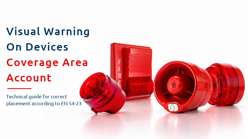
Correct placement of visual alarm devices cannot be determined simply by calculating room area and dividing it by a nominal area per device. Under the EN 54-23 approach, the objective is to provide visible warning within a three-dimensional volume under defined mounting conditions.
Two rooms with the same floor area may therefore require different device quantities because of ceiling height, columns, shelving, partitions, doors and occupant sight lines.
The exact product and variant code, EN 54-23 category, selected flash setting or power mode, certified coverage for that setting, mounting height and orientation, power consumption, environmental class and panel compatibility should be considered together.
Coverage calculation begins with geometry, but it is not complete until power demand, synchronisation and actual field visibility have also been verified.
A visual alarm device is intended to cover a three-dimensional volume rather than only a floor area. Even when the plan dimensions remain unchanged, a change in ceiling height can affect whether the device remains within its certified mounting limits.
Columns, racks, cabinets, partitions and corridor turns can also prevent the warning from being directly visible.
For this reason, dividing the total floor area by a single “square metres per device” value is not reliable. With circular coverage footprints in particular, total-area ratios can leave uncovered corners or gaps between neighbouring devices.
The source document addresses three main EN 54-23 categories:
|
Category |
Application approach in the source |
|
W |
Wall-mounted coverage approach |
|
C |
Ceiling-mounted coverage approach |
|
O |
Manufacturer-defined open coverage approach |
The selected category should be verified against the approved documentation for the actual product.
The coverage code in the manufacturer documentation describes the geometric volume covered under defined mounting conditions. Its exact format and meaning should be confirmed from the certificate, datasheet or other approved product documentation.
The source highlights errors such as treating W or C code figures directly as a radius, confusing diameter and radius, or using the coverage diameter directly as the permitted spacing between two devices.
For circular C-category coverage, the preliminary geometry can be converted into the largest square that fits inside the coverage circle:
a = y / √2 ≈ 0.707 × y
In the source, y is the coverage diameter. The spacing between two devices should not exceed a, while the distance from a wall to the nearest device should not exceed a/2.
For a C-3-15 device, the example gives a = 0.707 × 15 = 10.6 m with a maximum wall distance of 5.3 m.
The quick-reference values are:
|
Coverage diameter y |
Inscribed square side a ≈ 0.707 × y |
|
6 m |
4.2 m |
|
10 m |
7.1 m |
|
15 m |
10.6 m |
|
20 m |
14.1 m |
These values are a preliminary geometric reference. The final design should use the certified coverage conditions of the actual selected product.
Start with the exact model and variant code rather than only the product-family name.
Record the EN 54-23 category, selected flash setting or power mode, corresponding coverage code, mounting height and mounting orientation.
Power consumption and circuit load should not be separated from the geometric calculation. A setting that provides wider coverage may consume more current. Circuit capacity, voltage drop, standby/alarm duration and other loads on the same circuit should therefore be considered together.
Environmental/IP classification, indoor or outdoor suitability, synchronisation requirements and panel compatibility should also be recorded.
The programmed field setting should match the project calculation and the final as-built documentation.
For a rectangular room, the certified coverage footprint can initially be placed on the scaled plan as geometric blocks or circles.
This is only a preliminary check. Areas behind columns, high shelving, enclosed cabinets, partitions and door directions still need separate review.
For a ceiling device with circular coverage, adding circular areas alone can leave uncovered corners. The actual circles should be plotted on the plan and the room corners, wall boundaries and gaps between neighbouring devices should be checked.
The a = y / √2 method defines a square that fits inside the circular coverage area. It can therefore be used as an initial spacing module.
The correct workflow is to select the certified coverage information, apply the geometry to the plan, review sight-line obstructions, confirm the power calculation and finally verify real visibility during acceptance testing.
The source uses a room measuring 12 m × 8 m with a 3 m ceiling.
If the selected device has certified mounting and coverage geometry that can be represented by a 6 m × 6 m plan module, the preliminary estimate is:
ceil(12/6) × ceil(8/6) = 2 × 2 = 4 devices
This remains a preliminary result. Partitions, cabinets and visibility from the doorway still need to be checked.
The source states that a 6 m module corresponds to the inscribed square of a C-category device with a coverage diameter y of approximately 8.5 m.
If a C-3-15 device were used in the same room, a would be 10.6 m. The preliminary estimate becomes:
ceil(12/10.6) × ceil(8/10.6) = 2 × 1 = 2 devices
while the wall-to-device distance must still not exceed 5.3 m.
A lobby may appear small on plan, but its ceiling height may exceed the maximum certified mounting height for the selected C category.
Simply adding more devices does not correct this condition.
The source identifies three possible approaches: considering a more suitable C category, using wall-mounted W devices at an appropriate height, or evaluating a manufacturer-approved O-category geometry.
An incorrect mounting height cannot be corrected only by increasing device quantity. The selected product must first be suitable for the actual mounting height.
In a racked warehouse, theoretical ceiling coverage may not be enough. High racks create vertical obstructions that can block the visual signal.
A ceiling device may geometrically cover the warehouse floor while the signal is not directly visible within the aisles occupied by users.
Each aisle and working zone should therefore be analysed as a separate sight area. Device positioning should consider the rack direction and user movement.
Geometric coverage and real visibility are not the same thing.
In an L-shaped corridor, a single device may appear geometrically sufficient, while the corridor turn blocks the direct sight line.
A visible position should therefore be provided for each corridor leg. Doors and directional signs should also be considered as potential sight-line obstructions.
A flash setting that provides wider coverage may require more current.
The selected setting may therefore be impractical if circuit voltage drop, panel or output capacity, standby/alarm duration and other loads on the same circuit have not been checked.
The programmed setting should match the power calculation and as-built record.
A geometrically correct arrangement that cannot be electrically supported is not a complete coverage design.
Synchronisation requirements should also be considered. Where multiple visual alarm devices operate together, their behaviour and panel compatibility should be documented and verified during acceptance testing.
The first major error is determining device quantity from floor area alone.
Another is reading W or C coverage-code figures as a radius.
Using the coverage diameter directly as the permitted spacing between two devices can also produce uncovered areas. The inscribed-square method and wall-distance limit should be checked for circular coverage.
Adding more devices while exceeding the certified mounting-height limit is another error.
Using theoretical plan coverage in a racked warehouse or L-shaped corridor without assessing actual sight-line obstructions can also produce an incorrect layout.
Racks, cabinets, partitions, signs or other equipment added after installation may block visibility and should therefore be considered whenever the space changes.
Other problems include failing to include flash-setting current consumption and voltage drop in the calculation, failing to document synchronisation and panel compatibility, and having a different programmed field setting from the approved project setting.
At project stage, identify the spaces requiring visual warning and the basis for that requirement. Confirm room dimensions and mounting heights and include the exact product code and relevant W, C or O category in the project.
Show coverage volumes on scaled plans and sections. Include columns, shelving, partitions and other obstructions.
Calculate flash setting, current demand and circuit load, and document synchronisation and panel compatibility.
During installation, device position and orientation should match the design. Mounting height should remain within the certified limits and any equipment added after design that blocks visibility should be identified.
Verify that the programmed setting is the same as the project and power calculation and record the address/zone label and device code.
During commissioning and acceptance, activate every device under the correct alarm scenario. Verify direct visibility from relevant occupant positions and test synchronised behaviour where multiple devices operate together.
Testing should be completed under mains and backup power conditions.
The final as-built plan, device-setting schedule and test record should be delivered.
Can VAD quantity be calculated from room area alone?
No. Certified coverage volume, mounting height, room geometry and sight-line obstructions must be considered together.
What do W, C and O mean?
Under EN 54-23 they represent wall, ceiling and manufacturer-defined open-category mounting/coverage approaches respectively.
Can coverage radius be calculated from the candela value in a catalogue?
The project should use the product's approved coverage code and mounting geometry. An independent radius should not be assumed.
If the ceiling-height limit is exceeded, are more devices sufficient?
No. An incorrect mounting height cannot be corrected simply by adding devices. A suitable category or mounting solution is required.
Is a ceiling VAD always sufficient in a racked warehouse?
No. Shelving can interrupt sight lines, so aisles and working areas should be analysed separately.
How should spacing be assessed for circular coverage?
For the circular C-category example in the source, the preliminary no-blind-corner geometry uses a = y / √2 ≈ 0.707 × y. Device spacing should not exceed a and the wall-to-nearest-device distance should not exceed a/2.
Does a wider coverage setting affect the power calculation?
Yes. A wider coverage setting may require more current and should be checked against circuit capacity, voltage drop and the other circuit loads.
What should acceptance testing verify?
Activation, visibility, settings, synchronisation, power conditions and cause-and-effect operation should be verified and recorded.
Reliable visual alarm device coverage design cannot be based only on floor area or candela values. The certified W, C or O category, mounting height, coverage geometry, occupant sight lines, obstructions, flash setting, power consumption, voltage drop, synchronisation and panel compatibility should be considered together.
For circular C-type coverage, the a = y / √2 approach can be used to establish an initial no-blind-corner spacing module. Columns, shelving, partitions, corridor turns and other real sight-line obstructions must still be reviewed separately.
Before publication or application, the W/C/O code, coverage values, current consumption, synchronisation and compatibility information for the actual Finder product should be verified against current certificates and datasheets. The dimensions in the examples are not product declarations.
 TR