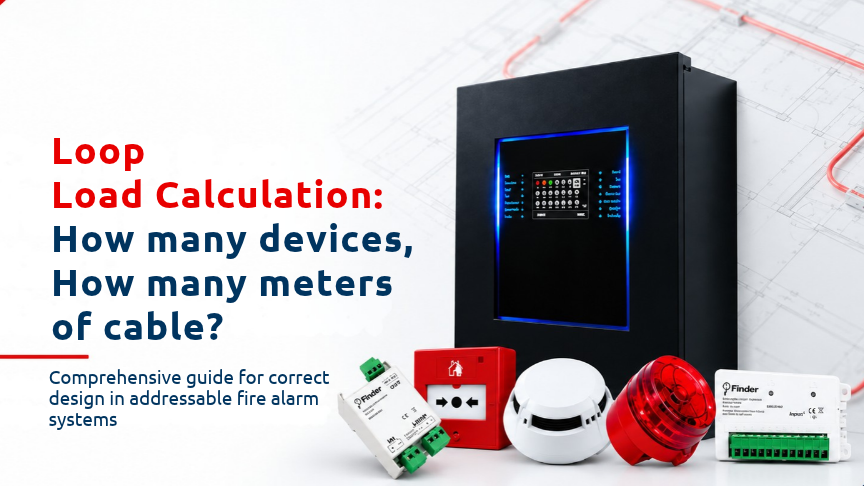
In an addressable fire detection system, loop capacity is not determined only by asking how many addresses remain available. The actual number of devices that can be used on a loop depends on standby and alarm current, cable cross-section and actual route, voltage drop, isolators, connection topology, panel protocol and supply limits, simultaneous alarm outputs and battery duty.
For this reason, figures such as 127, 200 or 250 devices, or 2,000 metres, should not be treated as universal limits. Such values may apply only to a particular panel, protocol, cable, load and manufacturer condition. A nominal capacity valid for one project should not be transferred directly to another panel or loop.
The fundamental principle is simple: available addresses on a panel do not by themselves prove that electrical loop capacity remains. Manufacturer capacity data, project calculations and field testing should be reviewed together.
|
Input |
What it determines |
|
Device load |
Standby/alarm current and outputs operating at the same time |
|
Cable |
Cross-section, length, resistance, screening and earthing conditions |
|
Topology |
Loop return, branch/T arrangements and isolators |
|
Panel |
Protocol, supply and capacity limits |
|
Energy |
Battery demand during standby and alarm periods |
The first step in loop calculation is the device schedule. Detectors, manual call points, sounder-beacons, input/output modules, relays, short-circuit isolators and any special interfaces should be listed by address.
Each row should include at least the device address, device type, standby current and alarm current from the manufacturer datasheet, quantity, operating scenario and any note relating to an isolator, branch or special load.
The critical point is that nominal address capacity and actual electrical capacity are not the same thing. A panel may support 127, 200 or 250 addresses, but the usable capacity may be limited earlier by the device mix, sounder-beacons active during alarm, modules, cable voltage drop and required reserve.
Therefore, the statement “the panel supports 250 devices, so 250 devices can be connected” is not sufficient. The number of devices matters, but so do their current consumption and which devices operate simultaneously in the alarm scenario.
Standby and alarm loads should be calculated separately. Some devices that draw little current in normal operation may impose a higher load during an alarm. Sounders, beacons, relays and input/output modules should therefore be reviewed separately under the alarm scenario.
The basic calculation is:
I_total = Σ(quantity × I)
First, sum the standby current of all devices. Then identify the devices active in the worst-case alarm scenario and calculate alarm current separately. Panel and auxiliary loads should also be included where applicable. Manufacturer design allowances or limits should then be applied. Finally, the calculated result should be verified by measurement at the furthest device.
The source document includes a representative example showing 80 detectors at 0.20 mA producing 16 mA, 10 manual call points at 0.10 mA producing 1 mA, 8 modules at 1.00 mA producing 8 mA and 12 sounder-beacons at 0.30 mA producing 3.6 mA. The total of 28.6 mA demonstrates the method only and is not a Finder product value.
Actual current values from the current device datasheets should be used for the real project. Outputs operating simultaneously should be determined from the actual cause-and-effect scenario.
Simply adding route length on a drawing is not sufficient. Cable cross-section, out-and-return conductor length, resistance, vertical routes, joints, service allowance, terminal/contact resistance and environmental conditions should all be considered.
Cable sizes such as 2×1.5 mm² or 2×2.5 mm² are examples only. Cable size should be selected according to load, route, voltage drop, fire rating and manufacturer requirements.
Likewise, a “2,000 m loop” statement is not a stand-alone design criterion. It may only apply to a particular panel, protocol, cable, load and test condition. The same figure should not be transferred to another system without manufacturer documentation and a verified project calculation.
The actual out-and-return cable route should be included. Vertical risers, floor transitions, bends, service allowances and joints all influence total resistance. Calculating cable length in one direction only is a common error.
The basic relationship is V_drop = I × R. Resistance should reflect the out-and-return conductor length, cable cross-section, joints and temperature effects.
The objective is to show that the most electrically unfavourable device retains the required minimum operating voltage during both standby and alarm conditions.
During commissioning, voltage should be measured at the furthest or most unfavourable device. An alarm scenario should be created, panel voltage and loop current recorded and the field result compared with the calculation.
Long cable routes, joints, terminals and field connections can affect the real result even when the theoretical voltage drop appears acceptable. Calculation and field verification should therefore be completed together.
The primary purpose of a short-circuit isolator is not to increase loop capacity or cable range. It is used to segment a fault so that other parts of the loop may remain available.
Isolators should be included in the device/current schedule and their behaviour assessed according to manufacturer documentation. The design should identify which section is affected by a short circuit.
If branch or T connections are used, confirm that the panel and protocol explicitly permit them. A branch/T topology used on another system should not automatically be copied into a new design.
The same applies to “2,000 m” or “250 devices” figures. They should not be transferred to another system without manufacturer topology rules and verified calculation.
Panel fault text should also clearly identify the affected site area so maintenance personnel can understand the fault quickly.
A loop should not consume all available capacity from the first day. A justified reserve allows for future alterations, device replacement and operational growth.
Reserve should not be considered only as spare addresses. Electrical load margin should also remain available. A new device may not be possible even if an address is free when current or voltage-drop limits have already been reached.
Address and current reserve should therefore be assessed together according to the project, operating plan and manufacturer limits.
Battery duty includes the panel, loop and auxiliary loads. Standby and alarm durations should follow the regulation or standard adopted for the project.
The source notes that some designs use 24-hour standby plus 30-minute alarm, but specifically states that this is not an automatic assumption for every project.
Battery calculation should include standby consumption and the loads active during alarm, together with the required duration and manufacturer-defined factors.
Mains-failure and battery verification should form part of commissioning and maintenance rather than leaving the result as a theoretical calculation only.
The address schedule should be compared with installed devices and panel addresses should match the as-built records.
Polarity and loop return continuity should be checked. Open-circuit, short-circuit and isolator tests should verify fault behaviour. Standby and alarm voltage should be measured at the furthest device, and alarm current and panel voltage should be recorded.
Sounders, beacons, modules and transmission outputs should be tested according to the actual cause-and-effect scenario. Cable joints, screening/earthing and transitions should be reviewed.
|
Check |
Verification |
|
Device schedule |
Matches installed devices and addresses |
|
Loop continuity |
Polarity and return verified |
|
Fault tests |
Open circuit, short circuit and isolator behaviour tested |
|
End voltage |
Standby and alarm measured at furthest device |
|
Alarm load |
Loop current and panel voltage recorded |
|
Outputs |
Sounder, beacon, module and transmission scenarios tested |
|
Documentation |
As-built, panel text and cable information current |
A reliable loop design combines a complete schedule, worst-case alarm load, actual cable route, voltage-drop calculation, isolator/topology check, battery verification and field testing.
Device currents, panel capacity, cable size and resistance, maximum loop length, voltage limits, isolator topology and battery durations should be verified using current Finder panel/device datasheets, installation manuals, applicable Turkish requirements and the standard adopted for the project.
Figures such as 127–250 devices or 2,000 metres should not be published as general Finder limits or transferred to another project without verification against the actual product and design conditions.
How many devices can be connected to one loop?
There is no universal number. Panel, protocol, device mix, current, cable and manufacturer limits determine actual capacity.
Is 2×1.5 mm² cable sufficient for every project?
No. Cable size should be selected according to load, route, length, voltage drop, fire rating and manufacturer requirements.
Why is alarm current calculated separately?
Sounders, beacons, relays and modules may draw more current during alarm than during standby.
Does an isolator increase loop capacity?
No. Its primary purpose is fault segmentation; it does not automatically increase loop range or device capacity.
How is battery duty calculated?
It is calculated from the panel, loop and auxiliary loads during the standby and alarm durations specified for the project.
Why should loop reserve be left?
It provides address and electrical capacity for future alterations, device replacement and operational growth.
How is voltage drop verified?
Cable resistance and minimum voltage at the furthest device are calculated, then verified by field measurement under standby and alarm conditions.
Does cable length include the return route?
Yes. The actual out-and-return route, vertical transitions, bends, joints and service allowance should be included.
The correct answer to loop design is not simply “how many devices?” or “how many metres of cable?” Actual capacity is determined by standby and alarm load, panel and protocol limits, real cable resistance and route, voltage at the furthest device, isolator and branch topology, reserve capacity and battery duty together.
The calculation file and field result should confirm one another. At project completion, the loop should be verified not only against nominal capacity but also under the worst-case alarm scenario and actual site conditions.
 TR