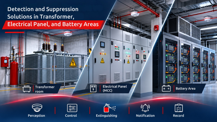
Transformer rooms, electrical panels and battery/energy-storage areas do not present the same electrical fire risk. Oil, arcing, cable insulation, power electronics and battery thermal runaway create different fire behaviours. For this reason, protection in these areas is not simply a matter of selecting a detector or a suppression device. Detection, control, energy isolation, ventilation, evacuation, suppression and event notification should be considered within one coordinated safety scenario.
According to the source document, the current Turkish Regulation on Fire Protection of Buildings, Article 65, addresses requirements relating to transformers and the use of an appropriate type of automatic fire suppression system. However, this content is not an application design for agent selection, nozzle placement, detection thresholds or extinguishing quantity. The actual product, risk analysis, applicable project standards and authorised-engineer verification are required.
The basic design principle is that detection should identify an early indication, suppression should be compatible with the selected equipment and environment, and the control logic should manage ventilation, evacuation, energy isolation and fire-service/operations notification according to the authorised scenario.
|
Area |
Priority risk |
Main design question |
|
Transformer room |
Heat, arcing and oil fire |
Is the transformer oil-filled or dry type, and how are ventilation and energy isolation managed? |
|
Electrical panel / MCC |
Local panel and cable fire |
What is the target enclosure volume and how does the selected agent affect the equipment? |
|
Battery / ESS |
Thermal runaway and re-ignition |
How are cell chemistry, BMS, gas/heat development and ventilation managed? |
These areas may exist within the same facility, but using a common safety architecture does not mean that the same detector or the same suppression approach should automatically be applied to all three.
The source document describes five primary layers: detection, control, suppression, notification and records. The detection layer monitors expected indications such as smoke, heat, flame or gas and produces alarm, pre-alarm or fault information. The control layer evaluates these signals through cause-and-effect logic and manages functions such as HVAC, energy isolation and delay.
The suppression layer releases only the agent defined by the authorised design and verified for the relevant risk, while also incorporating abort logic where required. The notification layer transfers information to the fire alarm panel, operations personnel, remote monitoring or the fire-service notification system. The record layer maintains event history, test results, revisions and as-built documentation.
The first distinction is whether the transformer is oil-filled or dry type. Fire load, smoke behaviour and possible fire spread can vary accordingly. Detection and suppression should therefore not be determined solely from room dimensions.
The source document states that all walls of the room in which the transformer is installed should provide 120 minutes of fire resistance. Ventilation is also important because it may dilute or extract smoke and influence detection behaviour.
Cable penetrations can create a path for fire or smoke to spread into adjacent spaces. Energy isolation should be coordinated with the detection and suppression scenario. For oil-filled transformers, oil containment is an additional design factor affecting the possible spread of a liquid fire.
Access should not be treated only as a maintenance issue. Safe access for the fire service and maintenance personnel is part of the emergency-management strategy.
The source does not define one universal detection technology for transformer rooms. Depending on whether the transformer is oil-filled or dry, ventilation conditions, temperature, access and the fire scenario, smoke, heat, flame or multi-technology detection may be considered.
Fire behaviour inside an electrical panel should be assessed separately from ceiling-level room detection. Cable ducts, busbars, arc flash, local hot spots and the internal panel volume may create localised risks.
The target fire volume should therefore be defined first. The project should determine whether the protected volume is the panel interior, the entire room or a combination of both.
When selecting a suppression agent, the assessment should include not only extinguishing performance but also electrical conductivity, residue, re-energisation and personnel exposure. The source therefore states that water or another agent should not be assumed automatically for an electrical panel. Agent selection should follow the equipment characteristics, energy-isolation strategy, re-ignition risk and the authorised fire strategy.
The design should clearly define which signal initiates energy isolation and what delay applies. It should also specify whether ventilation is shut down before suppression and when it can restart afterwards.
Manual abort is another important element. It should be confirmed that an authorised person can safely stop the discharge when required and that access and procedures support this function.
Battery and energy-storage systems require cell chemistry, module/cabinet arrangement, BMS alarms, thermal runaway, gas generation, ventilation and propagation to adjacent cabinets to be considered together.
Smoke, heat, gas and telemetry do not necessarily provide indications at the same time or in the same sequence. The BMS can monitor temperature, voltage and imbalance. Smoke detection may identify combustion products. Heat detection may indicate a hot spot or thermal runaway. Gas monitoring may provide another warning layer depending on the cell chemistry and risk analysis.
Ventilation is not only a comfort function; it can play a role in controlling the spread of gas and smoke. Cabinet separation and spacing are also part of the propagation assessment.
One of the key limitations stated in the source is that there is no single universal agent or universal threshold for battery systems. Agent selection should consider cell chemistry, cabinet volume, re-ignition, cooling, electrical safety, environmental conditions and manufacturer testing.
Detection should operate within the same cause-and-effect sequence as the BMS, ventilation, energy isolation and fire-service/operations notification. The presence of a smoke detector alone does not demonstrate that all battery-safety requirements have been addressed.
The source notes that the IEC 62933 family, NFPA 855 and UL 9540/9540A may become applicable depending on the contractual framework. The relevant edition and project scope should be verified by the authorised engineer.
System behaviour should be defined in advance for each event level. A pre-alarm may initiate notification to the operator or remote monitoring centre, but any selected delay must not compromise life safety.
A fire alarm may initiate evacuation, signal transfer and HVAC actions. Correct panel text and zone identification are important so that response teams are directed to the correct location.
When a suppression request occurs, the required preconditions and countdown logic should be checked. Manual abort should remain accessible. When discharge occurs, the agent release and event should be recorded and the occupancy procedure should be applied.
A critical fault may mean that the suppression system is not ready. In this case, the compensating measure should already have been defined.
Energy isolation is also part of the cause-and-effect matrix. Isolation should be authorised and backfeed risk should be controlled.
A key mistake identified in the source is treating the system as complete simply because a suppression cylinder has been connected to the detection panel. Volume, agent, preconditions, energy isolation, evacuation, ventilation and maintenance need to be designed together.
Before design begins, a risk inventory and fire scenario should be prepared. Transformer type, panel volume and battery chemistry should be recorded.
Ventilation, smoke extraction and energy isolation should be coordinated. The selected detection technology should correspond with the expected fire indication.
The suppression agent should be verified for compatibility with the equipment, personnel and environment. Cause-and-effect logic, delays and manual abort should be approved.
Fire-service and operations notifications should be tested, compensating measures should be defined for critical faults, and commissioning and maintenance records should form part of the project handover.
Commissioning involves more than checking each individual component. Detection, BMS, energy isolation, HVAC, suppression, manual stations, transmission and records should be verified as one chain.
For detectors, alarm, pre-alarm and fault scenarios should be tested. Signal transfer from the BMS or energy system and the corresponding energy-isolation action should be verified.
HVAC shutdown and restart behaviour should be tested against the approved scenario. For the suppression system, pre-discharge logic, required outputs and event records should be checked.
Manual initiation and abort functions should be tested. Remote monitoring or fire-service signal transfer should also be verified.
At cabinet and panel level, doors, enclosure volume and potential obstructions should be reviewed. Test results, revisions and responsible persons should be recorded.
The first error is assuming that transformer, electrical-panel and battery areas have the same fire behaviour. Their energy sources, fire development and suppression requirements differ.
Another error is relying only on a ceiling detector. Local indications and other sensor or telemetry layers may require separate consideration, particularly for panels and battery areas.
Failure to coordinate the BMS and the fire alarm panel is another critical issue. If battery telemetry and fire detection remain isolated from one another, the required cause-and-effect actions may be incomplete.
Other errors identified in the source include omitting ventilation and energy isolation from the matrix, selecting an agent without verifying equipment compatibility, failing to assess re-ignition and cabinet-to-cabinet propagation, and failing to test manual abort and evacuation under the actual scenario.
Failure to hand over maintenance procedures and post-event investigation requirements also reduces long-term system reliability.
A safe solution for transformer, panel and battery areas brings detection, suppression and electrical/process control together within a single cause-and-effect architecture.
Finder detection solutions and Defender suppression solutions should be considered within this integrated architecture. However, actual product and agent suitability, volume calculations, detection thresholds, energy isolation, BMS integration, ventilation and re-ignition procedures should be verified using current Finder/Defender documentation, Turkish regulations and the standards applicable to the project.
This content does not replace an application design.
Which detection is used in a transformer room?
Smoke, heat, flame or multi-technology detection is assessed according to whether the transformer is oil-filled or dry type, as well as ventilation, temperature, access and the fire scenario.
Can water-based suppression be used for an electrical panel?
Agent selection is based on the equipment, energy isolation, re-ignition and the authorised fire strategy; it should not be assumed automatically.
Is a smoke detector alone sufficient in a battery area?
Cell chemistry, thermal runaway, gas and heat development, ventilation and the manufacturer safety system should be assessed together.
Does a detection alarm automatically initiate suppression?
Only if the approved cause-and-effect scenario, risk analysis and authorised design permit it. Delay and evacuation logic should also be verified.
Can transformer and battery areas be protected by the same suppression system?
Fire behaviour and agent compatibility differ for each risk. A common system may only be selected after engineering analysis.
Does thermal imaging replace a fire alarm?
Thermal monitoring may provide support, but it does not automatically replace fire detection or suppression control.
Is battery-gas monitoring required?
Gas and ventilation monitoring may be required depending on cell chemistry, the enclosed volume, ventilation and the manufacturer risk analysis.
How is re-ignition managed after suppression?
Isolation, hot-spot monitoring, access, ventilation and re-energisation procedures are planned.
What is included in the system acceptance test?
Detector, alarm, interlock, energy isolation, suppression output, manual initiation and fault scenarios are recorded.
 TR