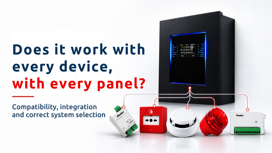
In fire detection and alarm systems, the fact that two products can be physically connected, operate at the same supply voltage or appear on a panel display does not by itself prove that they are compatible. True system compatibility requires physical and electrical conditions, communication protocol, firmware and product revisions, expected functions, system documentation and commissioning tests to be verified together.
This distinction is particularly important in addressable systems. An addressable loop is not simply a power circuit for field devices. It is also the manufacturer-specific digital communication channel between the panel and field devices. Supplying power to a device is therefore not enough. Message format, timing, addressing method, device profile, command set and fault supervision must all be supported by the panel.
The same principle applies to conventional systems. A device cannot be considered fully compatible simply because two wires can be connected and an alarm can be generated. Detector base, alarm current, end-of-line arrangement, alarm and fault thresholds, zone reset behaviour and circuit supervision should correspond with the panel documentation.
The correct question is therefore not “Is the voltage correct?” but “Is this exact panel-board-firmware-device combination documented and functionally compatible?”
|
Layer |
What should be checked |
|
Physical and electrical |
Supply, wiring, base, current, EOL component, thresholds and reset behaviour |
|
Protocol |
Message format, timing, addressing, commands and fault supervision |
|
Firmware and revision |
Panel, board and field-device hardware/software versions |
|
Functional |
Normal, alarm, fault, disabled and command behaviour |
|
Documented system compatibility |
Manufacturer matrix, EN 54-13 scope and related system evidence |
|
Commissioning and acceptance |
Alarm, fault, I/O and cause-and-effect testing |
Passing one layer does not mean that all other layers automatically pass. Operating at the same voltage covers only part of the electrical check.
Compatibility assessment usually begins with wiring and electrical limits. This is an appropriate starting point, but it is not the entire process.
In conventional systems, the fact that a device can be connected to a panel zone does not necessarily mean that the panel will interpret alarm and fault conditions correctly. The detector base and connection method, end-of-line component, alarm current, panel alarm and fault thresholds, zone reset behaviour and circuit supervision should all be reviewed together.
Statements such as “it provides a contact,” “it uses the same voltage” or “it is a two-wire device” are therefore not sufficient technical evidence. Panel documentation and field-device documentation should be compared.
In addressable systems, both power and digital data are carried over the loop. A device being electrically connected and its LED illuminating does not prove that the panel has correctly identified the device or supports all of its functions.
The protocol defines the common communication language and behaviour rules between the panel and the field device. Message format, timing, addressing, commands and the method used to report faults are all part of this structure.
Two addressable devices that are mechanically similar may use different communication languages. Fitting the same type of base, connecting to the same cable or operating within the same supply range does not prove addressable compatibility.
The term “open protocol” also does not automatically mean that every device using that protocol will work with every panel. The implemented protocol version, device profile, mandatory and optional commands and the exact combination tested by the manufacturer should still be verified.
For the project, the important point is the documented support status of the exact panel and device combination being proposed.
Gateways and other interfaces can be used to transfer defined data points to supervisory systems or to exchange specific functions between systems.
However, the presence of such an interface should not be interpreted as automatically turning a third-party loop device into a fully supervised and certified native panel device.
The data transferred through the interface should be clearly defined. Alarm, fault and other conditions, communication delay, fault transfer and fail-safe behaviour should be reviewed. The way the interface arrangement is addressed within the certification or system compatibility scope should also be checked.
A dry contact or standard supervisory interface does not mean that arbitrary devices from different manufacturers can be mixed on an addressable loop.
Different hardware or firmware revisions may exist under the same model code. A new device function may not be recognised by an older panel firmware version, while an older field device may not support all functions of a newer panel.
Before any firmware update, the existing configuration and event records should be backed up. Panel, board and device versions should be inventoried, and the manufacturer’s release notes and compatibility matrix should be reviewed.
The source document recommends a pilot loop or pilot-area test and a rollback plan before the update is applied more widely. After the update, the cause-and-effect matrix should be retested.
Device identification, alarm, fault, I/O, recording and cause-and-effect functions should therefore be verified again after a firmware change.
A device appearing on the panel display or having its address read does not prove full functional compatibility.
A compatible device should report the normal state correctly, generate the correct alarm state when required, transmit the correct fault information and show the correct condition when disabled. It should also respond as expected to supported panel commands.
Commissioning should therefore go beyond a simple “device detected” check. The functions required by the project should be tested using actual operating scenarios.
For input/output modules, the input state should be correctly displayed by the panel and an output command should produce the intended behaviour. Alarm, fault and disabled conditions should be correctly differentiated.
The source document describes EN 54-13 as a system approach to assessing compatibility and connectability between components of a fire detection and alarm system.
Individual EN 54 product documents remain important, but two separately documented products should not automatically be assumed to create a compatible system.
Document review should identify the exact panel model and firmware, the loop or zone board code and revision, and the exact model and variant of the field device. Support for the function or setting that will actually be used should also be verified, together with cable/topology and quantity limits.
Document date and revision matter. An older compatibility list or document may have been replaced by a newer revision. The current scope should therefore be verified rather than relying simply on the presence of a PDF in the project file.
For actual Finder panel, board, firmware and field-device combinations, current manufacturer compatibility lists and documentation should be used before making a product-specific compatibility decision.
Using products from different manufacturers within the same project is not the same as arbitrarily mixing addressable loop devices from different manufacturers.
According to the source document, mixed-brand arrangements may only be considered at clearly documented interfaces, within manufacturer-permitted limits and with function and fault transfer tested.
The fact that two systems exchange defined alarm or status information through an interface does not mean that an addressable detector from one manufacturer can be directly connected to another manufacturer’s loop.
Warranty responsibility for mixed systems should also be clearly defined during the quotation stage.
Compatibility risks can be significantly controlled before equipment reaches the site. The quotation should state the exact panel, board, firmware and field-device codes.
The current manufacturer compatibility matrix should be included. Maximum device quantity, loop load and cable limits should be verified, and the support status of every function or setting required by the project should be clearly stated.
Programming tools, required licences and access methods should be defined. Spare-parts availability, firmware support and product lifecycle support should also be stated.
System certification or compatibility scope should be documented, while commissioning, testing, training and as-built delivery should be included within the quotation scope.
Where mixed systems or special interfaces are used, warranty responsibility should be clearly assigned.
Commissioning is the final field verification of the compatibility claim. The real panel, board, firmware, cable and device combination should be tested using the project scenarios.
Devices should be confirmed as the correct model and address. Normal, alarm, fault and disabled states should be tested separately.
The device or module should respond correctly to supported commands from the panel. Input/output functions and the cause-and-effect matrix should be verified.
If firmware has been updated, device identification, alarm/fault, I/O, recording and cause-and-effect tests should be repeated.
Test results should be recorded at acceptance, and the as-built documentation should include the actual panel, board, firmware and field-device details.
Compatibility is not demonstrated by one document alone. The manufacturer compatibility matrix, relevant system evidence, project calculations and recorded commissioning tests should be used together.
One of the most common mistakes is assuming that the same voltage means full compatibility. Voltage is only one layer of the assessment.
Another is treating a physical connection or illuminated LED as proof of addressable compatibility. The device protocol and all required functions still need panel support.
It is also incorrect to assume that conventional devices are completely universal. Alarm current, base, EOL values, thresholds, reset behaviour and supervision can differ.
A gateway should not be treated as a universal solution to every compatibility problem. It should only be assessed for the defined data and functions it is intended to transfer.
Other important errors include failing to retest after firmware updates and assuming that individually documented EN 54 products automatically form a compatible system combination.
A reliable compatibility decision should not depend on one technical property. Physical and electrical suitability, protocol support, firmware and revision matching, functional behaviour, documented system scope and field acceptance tests should all be completed.
If the exact panel, board, firmware and field-device codes are not known, a definitive compatibility decision should not be made. A generic series name or product family should not be used as the basis for approving a combination.
The current manufacturer compatibility matrix should be compared with the project device list, and support for the functions that will actually be used should be verified. Once the system is installed, the document review should be completed with real alarm, fault and cause-and-effect testing.
Are two devices compatible if their voltage is the same?
No. Voltage is only one layer; protocol, firmware, electrical limits, function and the documented combination must also be verified.
Will an addressable detector work on another brand’s panel?
Generally, only combinations explicitly documented by the manufacturer should be considered. Physical connection or an illuminated LED is not proof of compatibility.
Are conventional devices completely universal?
No. Alarm current, base, end-of-line component, thresholds, reset and circuit supervision behaviour may differ.
Does a gateway solve compatibility problems?
Only for the defined data and functions. Delay, fault transfer, fail-safe behaviour and certification scope should still be reviewed.
Is retesting required after a firmware update?
Yes. Device identification, alarm/fault, cause-and-effect, I/O and recording functions should be verified again.
Are two separately EN 54-documented products automatically compatible?
No. Individual product documentation is important, but system compatibility of the combination must still be verified.
Can a mixed-brand system be used?
Only at clearly documented interfaces, within manufacturer-permitted limits and after function and fault transfer have been tested.
How is compatibility demonstrated?
The current manufacturer compatibility matrix, relevant system documentation, project calculations and recorded commissioning tests should be used together.
The general answer to “Does every device work with every panel?” is no. Compatibility in fire alarm systems cannot be reduced to connector type, supply voltage or physical similarity.
In addressable systems, protocol, firmware, product revision and panel support for the device profile are critical. In conventional systems, alarm current, base, end-of-line arrangement, thresholds, reset and supervision behaviour should all be reviewed.
EN 54 product documentation remains important, but separately documented products do not automatically form a compatible system. Current manufacturer compatibility matrices and the relevant system scope should be reviewed, exact product codes should be defined during procurement, and alarm, fault, I/O and cause-and-effect functions should be tested on site.
Before publication or a project-specific decision, actual Finder panel, board, firmware and field-device combinations, quantity/cable limits, EN 54-13 scope and certification claims should be verified using current compatibility lists and documentation.
 TR