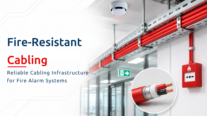
In a fire detection and alarm system, a cable is not merely a conductor connecting two points. Fire-resistance classification, conductor construction, cross-section, shielding, twisted-pair structure, circuit resistance, voltage drop, installation method, insulation and termination should be considered together.
An incorrect selection or installation in any of these areas may appear at the panel as an open circuit, earth fault, short circuit, loop communication fault, missing devices, intermittent fault or voltage collapse during an alarm condition.
For this reason, every fault displayed on the fire alarm panel should not automatically be attributed to the panel itself. Event timing, affected addresses, cable route, joints and terminals, shield/earth arrangement and measurement results should be assessed together.
The basic principle is to select the cable according to the alarm, monitoring and power-continuity function it performs within the system rather than only its price per metre. The final selection should be verified against the actual panel/device manual and the standard adopted for the project.
|
Input |
Effect on panel / system |
|
Fire resistance |
Helps critical functions continue during fire |
|
Conductor cross-section |
Resistance and voltage drop |
|
Pair construction |
Signal integrity and EMC |
|
Shielding |
Electromagnetic immunity |
|
Insulation |
Earth faults and environmental durability |
|
Installation |
Influence of power cables and mechanical damage |
|
Termination |
Terminals, shield and device-base connections |
The purpose of fire-resistant cabling is to contribute to maintaining critical circuit functions for a defined period during fire conditions.
Functions such as alarm, control, audible and visual warning, suppression initiation or fire-door control depend on more than the cable itself. Cable classification, routing, supports, tray systems, wall/floor penetrations, joint boxes and connection components should be considered together.
According to the source document, the minimum framework in Türkiye is described through Article 83 of the Regulation on Fire Protection of Buildings.
Signal and supply cables running from fire-control panels to audible and visual warning devices, voice-evacuation amplifiers and loudspeakers and emergency-control devices; the internal building sections of cables used to notify the fire service; communication and power cables between main, subsidiary and repeater panels; and cables supplying power to the panels are required to provide at least 60 minutes of fire resistance.
These cables should be tested and certified according to the relevant standards.
The source also states that, under Article 83/3, fire resistance may not be required for certain circuits that do not need to remain operational for an extended period after fire detection. This may include cables associated with manual call points, detectors and certain fire-control-panel circuits, together with electromagnetic door holders and similar equipment where loss of power does not create a hazardous condition.
For healthcare buildings, accommodation buildings occupied by more than 100 people and assembly buildings with more than 1,000 users, the source states that power and distribution cables and cable-containment materials should be halogen-free and should not produce toxic gases when exposed to fire.
Circuit integrity, flame spread, smoke and gas behaviour, mechanical protection, supports and fire-stopping at penetrations should therefore be treated as parts of the same cabling system.
A fire alarm panel will normally not display a message saying that the wrong cable has been installed. It reports the electrical or communication condition that has become abnormal.
A broken conductor, loose terminal or inadequate joint can appear as an open-circuit fault.
Damaged insulation, moisture or incorrect shield earthing may create an earth fault.
A crushed cable, incorrect stripping or metal contact may result in a short circuit.
High resistance, incorrect polarity or a shielding/EMC problem may appear as a loop communication fault.
Voltage drop, protocol disturbance or a branch-related problem may cause devices to disappear from the panel.
A vibrating joint, temperature-dependent contact or cable movement can produce intermittent faults.
When sounders or other outputs become active, inadequate cable size or power conditions may cause voltage problems under alarm load.
For this reason, diagnosis should not be based on the panel message alone.
Increasing conductor cross-section generally reduces resistance, but “larger is always better” is not a sufficient design rule.
Panel terminals and device bases, permitted cable bend radius, fire-resistance performance and the applicable installation standard also influence the correct selection.
Cable length should not be calculated using only a one-way route. The actual out-and-return route, vertical sections, joints and service allowance should all be included.
Standby and alarm current should be evaluated separately. The furthest device should be checked to confirm that the manufacturer's minimum operating voltage is maintained.
Cable resistance is not the only contributor to the circuit result. Joint and terminal resistance can also influence the total.
Environmental temperature and its effect on resistance should also be considered.
The design calculation should therefore be verified with field measurements during commissioning.
Shielded twisted-pair cable can help manage electromagnetic effects in addressable communication circuits.
However, an incorrectly connected shield can become a source of faults rather than a solution.
Earthing the shield at both ends or at an unsuitable point may create earth loops and interference. Leaving the shield completely unconnected may reduce EMC immunity.
Routing the loop cable close and parallel to power, motor or variable-frequency-drive cables can increase induced electrical noise.
Opening the twisted pair excessively at terminations can affect signal integrity. Mixing cable ends can create polarity or protocol problems.
One important warning in the source document is that “earth the shield only at the panel end” is not an automatic rule for every product or system.
Shield termination should follow the actual panel manufacturer's instructions, the project EMC design and the authorised engineering decision.
Even the correct cable can lose reliability when installed incorrectly.
Fire alarm cabling should be suitably separated from power, motor and variable-frequency-drive cables according to the project requirements.
Wall and floor penetrations should be closed using certified fire-stopping solutions.
Cable trays and supports should be designed so that the cable does not fall under fire conditions.
Sharp edges should not damage the cable sheath or insulation.
Joint boxes should remain accessible, identified and fitted with suitable terminals.
The manufacturer's minimum bend radius should be maintained.
Field address labels should correspond with the panel configuration and as-built documentation.
Fire resistance is therefore not a property of the cable alone. Supports, tray systems, penetrations, joint boxes and connection components also affect circuit integrity.
One common site error is selecting the cable without calculating the conductor size and actual total route.
Another is installing fire-resistant cable as though it were standard power cable.
Randomly earthing the shield at both ends and routing the loop cable with power cables can also cause problems.
Leaving terminals and joint points inaccessible, passing the cable over sharp edges without protection and failing to check polarity, loop return and isolators are further common errors.
Another important error is completing commissioning by simply resetting the panel without measuring end voltage, continuity, resistance and insulation condition.
If a fault repeatedly appears at the same address, the device should not immediately be replaced.
The device base, terminals, cable joint, route and environmental conditions should first be compared.
Commissioning begins with a visual inspection. Cable type, routing, supports, penetrations and labels should be reviewed.
Conductor and loop-return integrity should be checked through continuity testing.
Unwanted contact between conductors should be checked.
Insulation condition should be assessed for earth leakage and damaged cable sheath.
Total circuit resistance and the effect of joints should be measured.
Voltage should be checked at the furthest device under normal and alarm conditions.
Panel, address, alarm, fault and output functions should be tested.
The continued operation of critical control and warning functions should be verified under the relevant fire scenario.
Before measurements are made, the power condition and manufacturer test requirements should be checked.
Where required, cable ends should be disconnected from the panel and field devices before testing.
It should be confirmed that insulation-test voltage is not applied to connected electronic equipment.
Measurement results should be recorded together with cable identification, route and date.
After the connections have been restored, panel and field functional tests should be completed.
Megger-type insulation testing should not be performed unless the connected panel and devices permit the selected method. Manufacturer procedures and competent personnel are required to avoid damage to electronic equipment.
For recurring faults, the first question should be when the issue began.
Refurbishment, moisture, temperature, power changes or equipment changes may be related to the fault.
The affected area should then be defined: one device, one section, one loop or the whole system.
The operating condition in which the fault appears is also important. Does it occur during standby, during alarm, when sounders are operating or while HVAC/production equipment is running?
The route should be inspected for joints, crushing, water, rodent damage and sharp edges.
The panel record—open circuit, earth fault, short circuit or communication fault—should be compared with the physical findings.
After correction, recurrence and the new measurement results should be recorded.
Routine maintenance should verify that routing and labels correspond with as-built documentation, trays and supports are sound, fire-stopping remains intact and joint/terminal boxes are dry, accessible and identified.
Shield/earth connections should comply with the project requirements. Loop resistance, insulation and continuity records should be maintained.
Normal and alarm voltage at the furthest device should be measured, and recurring faults should be followed through to documented root-cause closure.
The handover package should record the cable manufacturer/model, cross-section and fire-resistance classification.
Cable routes, lengths and penetration details should be documented together with loop/zone information, address schedules and isolator locations.
Continuity, short-circuit, insulation, resistance and voltage measurements should be included.
The shield/earth diagram, terminal details, alarm/fault/function test records, product datasheets, installation manuals and conformity documents should also be provided.
Revision and as-built drawings and the maintenance plan should form part of the final package.
These records support not only project handover but also faster diagnosis of future faults.
Does fire-resistant cable completely prevent panel faults?
No. Reliable operation depends on the correct cable together with routing, joints, shielding, terminals, panel compatibility and testing.
Does increasing cable cross-section solve every problem?
No. Protocol, shielding, topology, insulation, installation and termination should also be checked.
What can cause an earth fault at the panel?
Damaged insulation, moisture, incorrect shield connection, metal contact or a field device may be responsible.
Can the shield be earthed at both ends?
It depends on the system. It should not be done unless permitted by the panel manufacturer and EMC design.
Can power and loop cables be installed in the same tray?
Project separation and routing rules apply; close parallel installation may increase interference risk.
Can insulation testing be performed with the panel connected?
Only a manufacturer-approved method should be used to avoid damaging connected electronic equipment.
What should be checked if the same address repeatedly reports a fault?
Check the device base, terminals, joints, cable route and environmental conditions before replacing the device.
How should cable length be calculated?
The actual out-and-return route, vertical sections, joints and service allowance should be included.
Is fire resistance only a property of the cable?
No. Supports, trays, penetrations, joint boxes and connection components also affect circuit integrity.
Can standard power cable be used in a fire alarm system?
Only where the project standard and manufacturer system permit it; critical circuits require verified fire performance.
How can a panel fault be distinguished from a device fault?
Panel records, address distribution, measurements and field substitution testing should be considered together.
Is recommissioning required after cable replacement?
Yes. Continuity, insulation, resistance, voltage, alarm/fault and cause-and-effect functions should be verified again.
Fire-resistant cabling is a broader engineering task than simply selecting a cable labelled as fire resistant.
Fire performance, conductor size, resistance, voltage drop, shielding, insulation, routing, supports, penetrations and termination should be assessed as one system.
Open-circuit faults, earth faults, short circuits, communication loss, missing devices or intermittent faults displayed on the panel do not always originate from the panel itself.
Correct diagnosis requires panel records, cable routing, joints, terminals, shield/earth arrangements and measurement results to be assessed together.
When cable selection, routing, support, shielding, termination, panel compatibility, measurement and maintenance are managed together, apparently “mysterious” panel faults can be traced back to their root causes more systematically.
Before publication or application, cable type, required fire-resistance period, shield/earth method, cross-section, maximum line length, voltage limits, measurement method and panel compatibility should be verified against current Finder panel/device documentation, current product documents, Turkish regulations and the standards adopted for the project. This content does not replace an approved project.
 TR